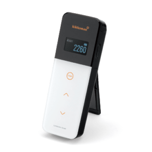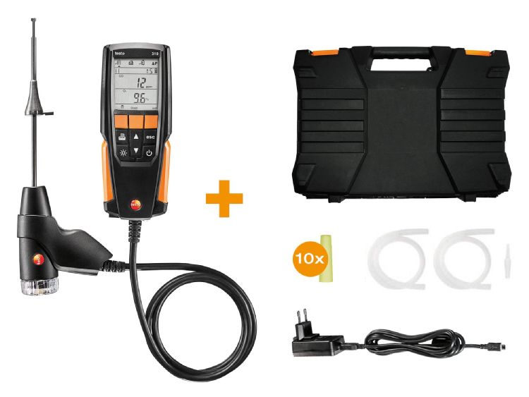
Testo 310 – Flue Gas Analyser (Standard Kit)
pressure
hours life
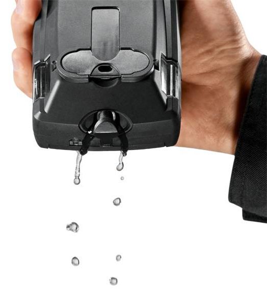
Being a systems mechanic you know only too well how tough things can get when
you€™re working out in the field. That€™s why your measuring tools need to be rugged
and reliable. Like the testo 310 flue gas analyzer. Designed especially for use in
the field.
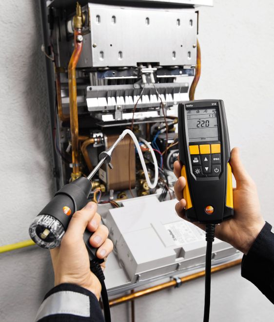
Product Description
The Testo 310 Flue Gas Analyser combines simple functions with a high level of
measurement accuracy, and is perfect for all basic measurements on heating systems.
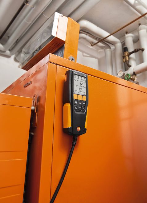
Long battery lifetimes of up to 10 hours guarantee high availability. It€™s easy
handling and compact design make the testo 310 a robust tool for daily work – even
when things get rough.
With its capability to perform both basic or more complex combustion analysis,
perform maintenance or safety checks, or confirm boiler efficiency, the fully
featured testo 310 residential combustion analyser is ready to provide accurate
analysis. The stainless steel probe and cone-stop is perfect for residential, and
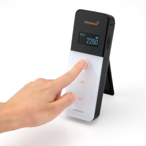
boiler efficiency applications. Simple top-of-display icons show you the current
measurement functions. After only 30 seconds, the 310 is ready to test. With five
different fuels to select from (Natural Gas, Propane, Fuel Oil 2%, Biomass 5%, Wood
20%), it provides the flexibility you need for all your residential combustion
analysis applications.
Measures:
Technical Data
| Temperature – TC Type K (NiCr-Ni) | |||||||||||||||||||||
|---|---|---|---|---|---|---|---|---|---|---|---|---|---|---|---|---|---|---|---|---|---|
| Measuring range | -20 to +100 °C | ||||||||||||||||||||
| Accuracy | ±1 °C | ||||||||||||||||||||
| Resolution | 0.1 °C | ||||||||||||||||||||
| Reaction time | < 50 s | ||||||||||||||||||||
Temperature (ambient temperature)
| Temperature – TC Type J (Fe-CuNi) | |||||||||||||||||||||
|---|---|---|---|---|---|---|---|---|---|---|---|---|---|---|---|---|---|---|---|---|---|
| Measuring range | 0 to +400 °C | ||||||||||||||||||||
| Accuracy | ±1 °C (0 to +100 °C)
±1.5 % of mv (> 100 °C) |
||||||||||||||||||||
| Resolution | 0.1 °C | ||||||||||||||||||||
| Reaction time | < 50 s | ||||||||||||||||||||
Temperature (flue gas)
| Flue gas O‚‚ | |||||||||||||||||||||
|---|---|---|---|---|---|---|---|---|---|---|---|---|---|---|---|---|---|---|---|---|---|
| Measuring range | 0 to 21 Vol.% | ||||||||||||||||||||
| Accuracy | ±0.2 Vol.% | ||||||||||||||||||||
| Resolution | 0.1 Vol.% | ||||||||||||||||||||
| Reaction time | 30 s | ||||||||||||||||||||
| Flue gas Draught | |||||||||||||||||||||
|---|---|---|---|---|---|---|---|---|---|---|---|---|---|---|---|---|---|---|---|---|---|
| Measuring range | -20 to +20 hPa
±0.03 hPa (-3 to +3 hPa) |
||||||||||||||||||||
| Accuracy | ±1.5 % of mv (Remaining Range) | ||||||||||||||||||||
| Resolution | 0.01 hPa | ||||||||||||||||||||
| Flue gas degree of effectivity, Eta (calculated) | |||||||||||||||||||||
|---|---|---|---|---|---|---|---|---|---|---|---|---|---|---|---|---|---|---|---|---|---|
| Measuring range | 0 to 120 % | ||||||||||||||||||||
| Resolution | 0.1 % | ||||||||||||||||||||
| Flue gas loss (calculated) | |||||||||||||||||||||
|---|---|---|---|---|---|---|---|---|---|---|---|---|---|---|---|---|---|---|---|---|---|
| Measuring range | 0 to 99.0 % | ||||||||||||||||||||
| Resolution | 0.1 % | ||||||||||||||||||||
| Flue gas CO‚‚ calculation (calculated from O‚‚) | |||||||||||||||||||||
|---|---|---|---|---|---|---|---|---|---|---|---|---|---|---|---|---|---|---|---|---|---|
| Measuring range | 0 to CO‚‚ max (Display range) | ||||||||||||||||||||
| Accuracy | ±0.2 Vol.% | ||||||||||||||||||||
| Resolution | 0.1 Vol.% | ||||||||||||||||||||
| Pressure measurement | |||||||||||||||||||||
|---|---|---|---|---|---|---|---|---|---|---|---|---|---|---|---|---|---|---|---|---|---|
| Measuring range | -40 to +40 hPa | ||||||||||||||||||||
| Accuracy | ±0.5 hPa | ||||||||||||||||||||
| Resolution | 0.1 hPa | ||||||||||||||||||||
| Flue gas CO (without H‚‚-compensation) | |||||||||||||||||||||
|---|---|---|---|---|---|---|---|---|---|---|---|---|---|---|---|---|---|---|---|---|---|
| Measuring range | 0 to 4000 ppm | ||||||||||||||||||||
| Accuracy | ±20 ppm (0 to 400 ppm)
±5 % of mv (401 to 2000 ppm) ±10 % of mv (2001 to 4000 ppm) |
||||||||||||||||||||
| Resolution | 1 ppm | ||||||||||||||||||||
| Reaction time | < 60 s | ||||||||||||||||||||
| General technical data | |||||||||||||||||||||
|---|---|---|---|---|---|---|---|---|---|---|---|---|---|---|---|---|---|---|---|---|---|
| Dimensions | 201 x 83 x 44 mm | ||||||||||||||||||||
| Operating temperature | -5 to +45 °C | ||||||||||||||||||||
| Display type | LCD | ||||||||||||||||||||
| Display function | | Power supply |
Storage temperature |
<-20 to +50 °C |
Weight |
<(with probe) Approx. 700 g |
| |||||||||||||||
Applications
Draught measurement in the flue gas duct
Draught measurement is actually a differential pressure measurement. This
differential pressure occurs between two sub-areas as a result of a difference in
temperature. This is turn generates a flow to compensate. In the case of flue gas
systems, the difference in pressure is an indicator of the €œchimney flue draught€.
This is measured between the flue gas and ambient air at the measurement orifice at
the core of the flue gas flow.
To ensure the flue gases are safely transported through the chimney there must be a
differential pressure (chimney flue draught) for boiler systems that work with low
pressure.
If the draught is permanently too high, the average flue gas temperature increases
and therefore flue gas loss. The level of efficiency drops.
If the draught is permanently too low, oxygen may be lacking during combustion,
resulting in soot and carbon monoxide. This will also cause a drop in the level of
efficiency.
Ambient CO measurement in the heated environment
Carbon monoxide (CO) is a colourless, odourless and taste-free gas, but also
poisonous. It is produced during the incomplete combustion of substances containing
carbon (oil, gas, and solid fuels, etc.). If CO manages to get into the bloodstream
through the lungs, it combines with haemoglobin thus preventing oxygen from being
transported in the blood; this in turn will result in death through suffocation.
This is why it is necessary to regularly check CO emissions at the combustion
points of heating systems, and places often frequented by people (in our case,
where the combustion systems for hot water generation are), and in the surrounding
areas.
Measuring the flue gas parameters of the burner (CO, O2, and temperature, etc.)
The flue gas measurement for a heating system helps to establish the pollutants
released with the flue gas (e.g. carbon monoxide CO) and the heating energy lost
with the warm flue gas. In some countries, flue gas measurement is a legal
requirement. It primarily has two objectives:
1. Ensuring the atmosphere is contaminated as little as possible by
pollutants; and
2. Energy is used as efficiently as possible.
Stipulated pollutant quantities per flue gas volume and energy losses must never be
exceeded.
Measurement in terms of results required by law takes place during standard
operation (every performance primarily using the appliance). Using a Lambda probe
(single hole or multi-hole probe), the measurement is taken at the centre of flow
in the connecting pipe (in the centre of the pipe cross-section, not at the edge)
between the boiler and chimney/flue. The measured values are recorded by the flue
gas analyzer and can be logged either for print out or transfer to a PC at a later
stage.
Measurement is taken by the installer at commissioning, and if necessary four weeks
later by the flue gas inspector/chimney sweep, and then at regular intervals by the
authorised service engineer.
Measuring pressure on burners (nozzle pressure, gas flow pressure, etc.)
Standard readings taken during services of domestic heating systems include
checking the gas pressure on the burners. This involves measuring the gas flow
pressure and gas resting pressure. The flow pressure, also called supplied
pressure, refers to the gas pressure of the flowing gas and resting pressure of the
static gas. If the flow pressure for gas boilers is slightly outside the 18 to 25
mbar range, adjustments must not be made and the boiler must not be put into
operation. If put into operation nonetheless, the burner will not be able to
function properly, and explosions will occur when setting the flame and ultimately
malfunctions; the burner will therefore fail and the heating system will shut down.
Accessories
Spare particle filter, compact probe; 10 off
Testo fast printer IrDA with wireless infrared interface; 1 roll thermal paper; 4
AA batteries
USB mains unit incl. cable
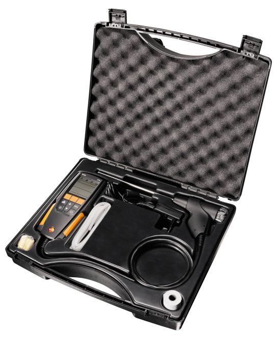
Delivery Scope
testo 310 – Flue Gas Analyser, Hard case, rechargeable battery, usb mains cable,
silicon hose for pressure, 5 x filters, calibration protocol, 180mm probe with
cone, spare pressure plugs.